Photogrammetry area

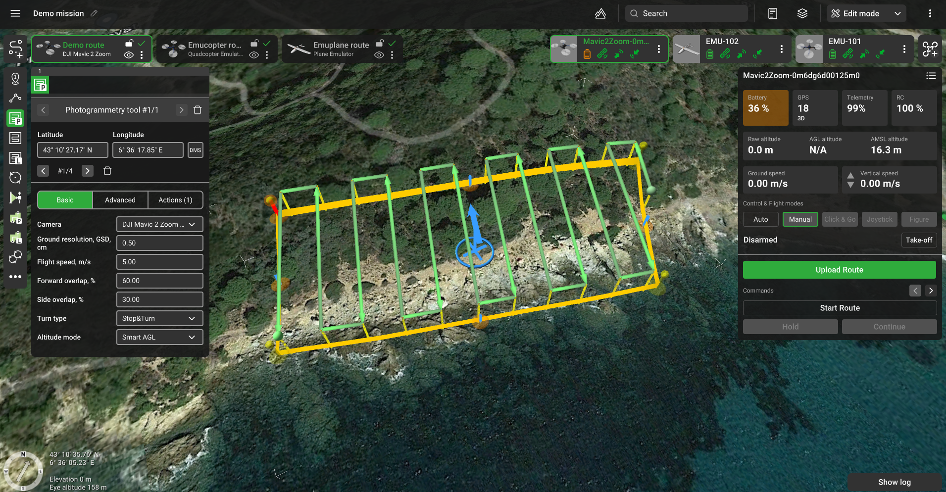
Photogrammetry area flight plan
Route points are placed at the same height relative to the ground. This height is calculated based on camera settings and set GSD value. Calculated parameters (number of passes, number of camera shots, etc.) are displayed in the route log window. The photogrammetry tool is available for UgCS PRO, UgCS EXPERT, and UgCS ENTERPRISE licenses.
Note: Photogrammetry tool requires a selected camera as a payload. The camera must have properly specified (positive) values of focal distance, sensor size (width and height), and sensor resolution (horizontal and vertical).
Additionally, to all standard options, these features are available for the Photogrammetry tool:
Basic
Camera – payload assigned to a profile. In the case of multiple cameras assigned to the profile, it is possible to select which camera to use.
Ground resolution (GSD, cm) – approximate ground resolution for resulting images (in centimeters per pixel).
Forward overlap (%) – the ratio of the overlap in neighboring frames (consecutive by a motion vector, see the scheme below). Value is set in the range from 1% to 90%.
Side overlap (%) – the ratio of the overlap in neighboring frames (placed in neighboring rows, see the scheme below). Value is set in the range from 1% to 90%.
Altitude mode – AMSL, AGL, Smart AGL, or Rangefinder to set Flight height.
Altitude AMSL - calculated from the lowest point using GSD. However, the number of shots required to meet forward overlap and side overlap constraints are calculated using the altitude difference between the calculated flight altitude AMSL and the highest point of the area.
Advanced
AGL Tolerance,m – allows flying straight trajectories over the slightly waved landscape, by specifying how precisely the UAV should follow the required altitude above ground. To maintain a specified height additional waypoints will be added if the height difference is larger than the AGL tolerance. The smaller the AGL tolerance value, the greater the number of waypoints will be generated. If AGL tolerance is set to 0 (zero) UAV’s altitude will be constant throughout the route, but many additional waypoints will be added.
Direction angle - used to change the direction of the main scanning progress. By default, the algorithm calculates a route scan in a bounded polygon so that the main course of the scan performs in the direction of "South-North".
Overshoot, m – adds extra segment to both ends of each survey line to allow extra space for turns.
Overshoot speed, m/s - option to decrease/increase vehicle speed for overshoot segment while passing turns.
Double grid - if enabled, add a second grid to the survey at a 90-degree angle according to the first grid.
Additional waypoints – if the flag is cleared, the algorithm generates only the turning points. If the flag is set, additional waypoints for camera shooting will be generated depending on overlap and camera settings.
Allow partial calculation – option to allow route calculation in these cases:
• The part of the route exceeds the maximum AMSL of the route
• Relief height is unavailable at some point(s) of route
• The part of the route that exceeds the maximum fence radius
• The part of the route in the No-fly zone (NFZ)
No action at last point – remove action for the last waypoint.
Camera top facing forward – concerns the camera orientation to the motion vector. The flag assumes the camera is oriented so that the frames overlap over the upper frame boundary motion vector. If the flag is removed, the frames overlap along the lateral frame boundary.
No action at last point – removes action for the last waypoint.
To Move / Rotate segment - select+hold the blue circle in the center to drag and drop the Area scan segment to another location. Select+hold circle’s rim to rotate the whole segment.
Note: For those pilots who use autopilot that supports camera triggering by distance or time, there is an automated algorithm that calculates and sets the correct parameters. It is not necessary to use this approach with Actions in every point parameter.

where 'fo' - forward overlap, 'so' – side overlap
Calculation:
- Calculate the altitude required for camera recording:
a. heightAgl = ( f GSD sensorWidthPx ) / sensorWidth;
b. heightAgl = ( f GSD sensorHeightPx ) / sensorHeight;
c. Selected minimum value calculated of heightAgl. - Calculate the frame size:
a. frameWidth = ( sensorWidth heightAgl ) / f;
b. frameHeight = ( sensorHeight heightAgl ) / f.
where 'f' is True focal distance
The scanning area is partitioned into frames of calculated sizes with given overlaps. The direction of passage is selected using the Direction angle. The route is formed as a 'snake'.
Updated about 2 months ago